 English
 中文简体
中文简体 Español

Cat:Wire Wheel Brush
Made from twisted wire filaments, this brush is used extensively in industrial and maintenance applications for tasks th...
See Details
Thin sheet materials behave differently during stamping because there is less material available to resist pressure and maintain shape. A sheet that looks stable before processing may bend, shift, or develop unwanted marks once force is applied. For manufacturers working with small metal parts, choosing a suitable Sheet Metal Stamping Die therefore starts with the material rather than the machine alone.
Material thickness influences how a sheet reacts when it enters the die. During cutting, the material needs enough support around the working area. During forming, pressure needs to be distributed in a controlled way so the part can take shape without unnecessary distortion. A die designed around a thicker material may not provide the same results when used with a thinner sheet.
Part shape matters as well. A flat piece with a simple outline places different demands on a die compared with a part containing narrow sections, small openings, or several formed areas. The more sensitive the shape is to movement, the more carefully the die needs to guide and hold the material.
Selection also needs to consider how the part will be produced. A die used mainly for cutting may have different requirements from one intended to combine cutting and forming. Looking at the entire production process helps avoid choosing a die based on a single feature.
Before production begins, several questions can help clarify the requirement:
Answering those questions gives a more practical starting point than simply selecting a die according to equipment size.
Thickness has a direct relationship with how sheet metal responds during stamping. A thinner sheet may move more easily under pressure, while a thicker sheet can resist deformation for longer. Such differences influence the working relationship between the cutting parts, supporting surfaces, and positioning elements.
During cutting, the material needs to separate along the intended outline. Too much movement around the working area can affect the edge and overall shape. Thin sheets can require closer attention because even a small change in positioning may become visible on the finished part.
Forming creates another set of considerations. Bending a thin sheet does not simply mean applying less force. The shape of the supporting surface, the direction of movement, and the way material flows around the forming area all affect the result. Poor support can leave a part with an uneven shape even when the original sheet was flat.
Material condition should be considered alongside thickness. Different metal sheets can respond differently during processing, depending on their flexibility and surface condition. A die intended for one material may need adjustment before being used for another material with a similar thickness.
A useful way to view the relationship is:
Material thickness → Material response → Die support → Working movement → Finished shape
Rather than treating thickness as an isolated specification, designers can use it as one part of a larger assessment. Material behavior, part geometry, and processing method need to work together.
A suitable die structure gives the sheet enough guidance and support throughout the working cycle. Thin material can be easier to disturb, especially when the sheet moves between different working areas. Stable positioning therefore becomes an important part of die design.
Upper and lower sections need to move in a controlled relationship. During cutting or forming, the working parts should approach the material along the intended path. A stable guiding arrangement helps reduce unwanted movement and makes the process easier to control.
Positioning areas deserve attention as well. When a sheet is not held in the correct location, holes, edges, or formed sections may shift away from their intended positions. Such movement can become more noticeable when several operations are performed on one part.
Different product shapes can call for different structural arrangements. A simple flat component may need a relatively straightforward supporting layout, while a shaped component may require additional support around narrow or flexible sections.
For thin materials, a practical structure often focuses on three basic needs:
A well‑planned structure does not necessarily mean adding more components. Unnecessary parts can make maintenance and adjustment harder. What matters is whether each structural element has a clear role in controlling the material and supporting the required operation.
Clearance describes the working space between mating cutting parts. Its relationship with sheet thickness can influence how cleanly material separates during a cutting operation.
When the working space is not well matched to the material, several changes may appear along the cut edge. The edge can become rougher, the part may show unwanted deformation, or the working parts may experience greater wear during repeated use. Thin material can make such differences easier to notice because the sheet has less resistance during cutting.
Clearance should therefore be considered according to the material being processed and the type of operation involved. Cutting a simple outer shape does not necessarily require the same arrangement as producing an opening inside the sheet.
Part geometry matters too. A small opening, narrow section, or closely spaced feature can place more pressure on the surrounding material. Designers need to consider how much material remains around each working area rather than looking only at the overall sheet thickness.
During production, clearance can gradually change as working surfaces wear. A die that produces a stable result during initial use may behave differently after extended operation. Regular inspection can help identify changes before they affect part quality.
For thin sheets, useful checks include:
Clearance is only one part of the die design. Combining suitable spacing with stable guidance and material support provides a more balanced approach to thin sheet processing.
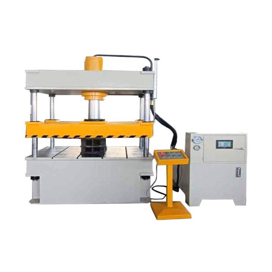
Thin sheet metal can move more easily than a heavier sheet, especially when only a small section is being worked. Without enough support, pressure from the die can cause bending or movement before the cutting or forming operation is completed.
Support becomes particularly important around openings and narrow sections. When a large area of sheet is removed, the remaining material may have less strength to maintain its position. A suitable supporting arrangement helps keep the sheet in place while the working parts move through their cycle.
Feeding creates another challenge. Material needs to reach the correct position for each operation, and repeated movement can gradually introduce small positioning changes. A stable feeding path can help maintain consistent placement from one operation to the next.
For forming work, support needs to follow the shape of the part. Holding a flat area firmly does not necessarily control a nearby curved or bent section. Supporting surfaces should therefore be considered in relation to how the material changes shape during processing.
| Working Requirement | Possible Concern With Thin Sheet | Design Focus |
|---|---|---|
| Cutting an outer shape | Sheet movement or edge changes | Stable positioning and support |
| Producing an opening | Local deformation around the opening | Suitable working space and guidance |
| Forming a bend | Uneven movement during shaping | Controlled support around the forming area |
| Repeated feeding | Position may shift between operations | A clear and stable feeding path |
| Narrow part sections | Greater tendency to move | Support near sensitive areas |
A Sheet Metal Stamping Die intended for thin materials should therefore be considered as a complete working system rather than a group of separate parts. Material thickness, die structure, working space, and support all influence how the sheet behaves during production.
Once those basic conditions are clear, attention can move toward the level of dimensional control required by the finished component. Parts with tighter shape requirements may call for a different approach to die design, which brings Precision Stamping Die considerations into the selection process.
Some thin metal parts need closer control over their shape, openings, or position during production. In such cases, a Precision Stamping Die may be considered when ordinary die arrangements cannot provide enough control for the intended part structure.
Precision does not simply mean making every part of a die more complicated. It relates to how well the die can keep the material in the intended position and guide each working movement. For thin sheets, even a small shift during processing can affect a hole, edge, or formed section, so stable movement becomes an important concern.
Part design gives useful clues when choosing the die structure. A simple flat component with a broad outline may be relatively easy to support. A component with narrow edges, closely positioned openings, or several shaped areas requires more attention because less material is available to keep the part stable.
Production sequence matters as well. When several operations are carried out on one component, each step can influence the next one. A small change during an earlier operation may become more noticeable after later cutting or forming.
A suitable die should therefore be considered according to the actual part rather than the word “precision” alone. Questions worth checking include:
Different operations place different demands on thin sheet materials. Cutting, opening, bending, and forming may all use a stamping process, yet the way material behaves during each operation is not the same.
Cutting mainly focuses on separating material along a planned outline. Stable positioning and suitable working clearance are important because unwanted movement can change the edge or shape.
Producing an opening requires attention around a smaller working area. When the opening is close to another feature, the remaining material may have less room to absorb the force of the operation. Support around the working area can therefore influence the result.
Bending changes the shape without completely separating the material. During such work, the sheet needs to move along a controlled path while the surrounding areas remain supported. A die designed only for cutting may not suit a forming task.
Some components require several operations. In such situations, the order of each step should be considered during die planning. An early operation can change the shape or stiffness of the sheet, affecting how it behaves in a later stage.
A simple production sequence may look like:
Positioning → Cutting → Forming → Final shaping → Part removal
Each stage needs to work with the next one. Choosing a Sheet Metal Stamping Die according to the complete process can reduce problems caused by treating every operation separately.
Part shape often determines how a thin sheet needs to be supported during stamping. A broad, flat component usually has more material available around the working area, while a narrow or irregular shape may move more easily.
Small openings can create another concern. When several openings are placed close together, the material between them becomes narrower. During stamping, such areas may require careful support so that the surrounding sheet does not shift or bend.
Long and narrow sections can behave in a similar way. Even when the overall part is not large, a slender section may have limited support during cutting or forming. Die structure should account for how that section moves under pressure.
The location of each feature matters as well. A hole positioned close to an edge can create different conditions from one placed near the center of a sheet. A formed section near another formed area may require a different working arrangement from an isolated feature.
For that reason, die selection can begin with the part drawing and move outward toward the production process. Useful information includes:
Looking at the part as a complete shape makes it easier to decide where support, guidance, and working areas need to be placed.
A die may appear suitable during design review, yet actual stamping can reveal issues that are difficult to see on a drawing. Trial production gives manufacturers an opportunity to observe how the material behaves when the die, sheet, and machine work together.
The finished part should be checked from several angles. Edge condition is one useful point, especially for parts produced through cutting. Holes should remain in their intended positions, while formed areas should keep the planned shape.
Material movement deserves attention during the working cycle. A sheet that shifts slightly during one operation may cause larger positioning changes when several operations follow one another.
The feeding process should be observed as well. Smooth movement into the working area helps maintain consistent positioning. Problems with feeding can sometimes look like die problems even though the cause lies in how the material enters the machine.
Trial production can focus on a few practical observations:
Such checks provide useful information before regular production begins. A small adjustment at the trial stage can be easier to manage than changing the die after it has been integrated into a longer production process.
Thin materials can make die condition easier to notice because small changes in working surfaces may affect the finished part. Wear around cutting or guiding areas can gradually change how the sheet is positioned or separated.
Regular inspection does not need to focus only on visible damage. Changes in part shape, edge condition, or positioning may provide early signs that a working area needs attention.
Clearance should be checked as well. Repeated contact can change the relationship between working parts over time. Once the working space changes, the material may no longer separate or form in the same way as it did during initial production.
Guiding and positioning components deserve regular attention. A loose or worn guiding area can affect alignment during each cycle, while a change in material support may allow thin sheets to move more easily.
Basic maintenance can include:
Maintenance should follow the actual working conditions of the die. A tool used for thin sheet production may require attention to different areas from one used for thicker material or a different production process.
Selecting a suitable die starts with clear information about the material, part, and production process. Thickness alone does not provide enough information because two sheets with similar thickness can behave differently during stamping.
Material condition should be described along with the required operation. Cutting, opening, bending, and forming each create different movement patterns, so the die needs to be designed around what actually happens during production.
Part drawings can help define the physical requirements. Dimensions, openings, narrow sections, bends, and mounting relationships give the die designer a clearer view of where support and guidance may be needed.
Machine conditions should be considered at the same stage. Available installation space, feeding direction, working movement, and part removal can all influence the die structure.
A practical selection process can follow a simple order:
Material → Part shape → Operation → Support → Die structure → Trial production
Starting with material behavior helps avoid designing around assumptions. Part shape then shows where control is needed, while the production method determines how the die should work with the machine.
For thin materials, a suitable Sheet Metal Stamping Die is closely connected with stable support, controlled movement, and proper working clearance. When part requirements call for closer dimensional control, a Precision Stamping Die may offer a more suitable structural approach.
Good die selection is therefore less about choosing a particular die type from a list and more about matching the tool to the way the sheet will actually move during production. A clear understanding of material behavior, part shape, working conditions, and maintenance needs gives manufacturers a practical basis for making that decision.
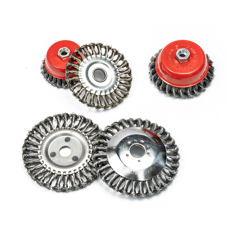
Made from twisted wire filaments, this brush is used extensively in industrial and maintenance applications for tasks th...
See Details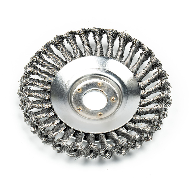
Its disc-shaped design, with tightly twisted wire bristles, provides uniform contact with the surface, making it ideal f...
See Details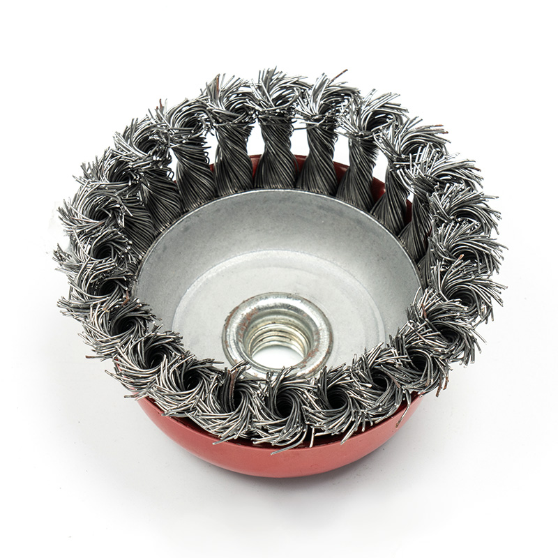
Featuring a bowl-shaped configuration and twisted wire bristles, this brush is suitable for industrial and automotive ap...
See Details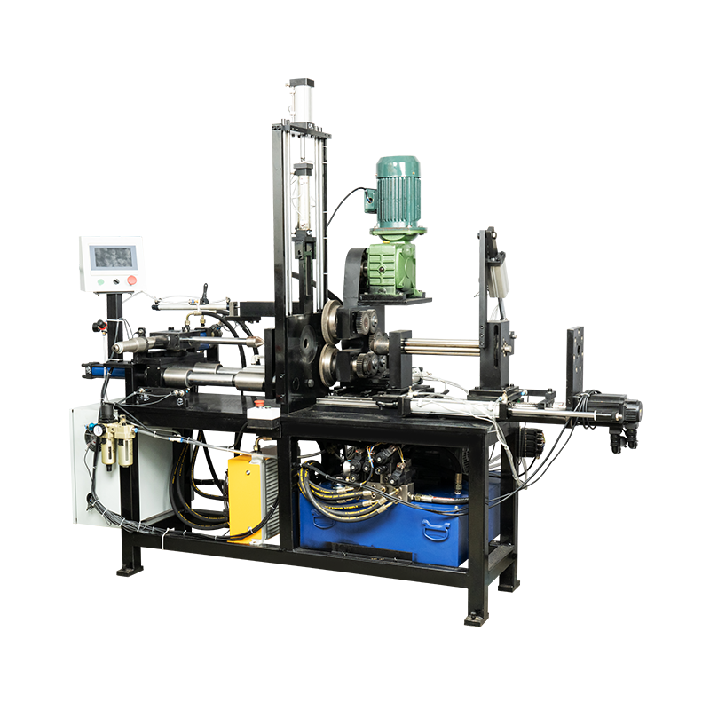
The Curved Brush Chip Cleaning Machine is engineered to solve common challenges in chip manufacturing, where cleanliness...
See Details
We warmly welcome all industrial and trade companies, converters, abrasives and tool agents and distributors to join us, enjoy Tarun's platform, develop their own markets, and share world resources!
 Email:
 Phone:
+86-18867586928
 Address:
Xiaxichi Industrial Zone, Gushan Town, Yongkang City, Jinhua City, Zhejiang Province

Scan the QR code
Copyright © Yongkang Tarun Technology Co., Ltd.

Metal Processing Automatic Machine Factory

+86-18867586928


Contact Us